The INI file “dhcpsrv.ini” is the configuration and the “database” for the DHCP Server. Its location is in the same directory as the dhcpsrv.exe file. Here are typical examples of the INI file content:
- Example 1: The server has only one NIC and manages clients on the same subnet
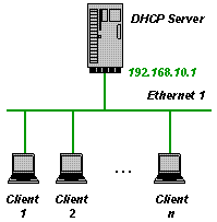 This is a very simple example and the INI file looks like this:
[General]
SUBNETMASK=255.255.255.0
ROUTER_1=192.168.10.1
DNS_1=192.168.10.1
[Settings]
IPPOOL_1=192.168.10.2-49
This manages the IP addresses 192.168.10.2 until 192.168.10.49. But be aware that all clients connected to the subnet 192.168.10.X get IP addresses assigned. Please make sure that you don’t get in conflict with other DHCP Servers.
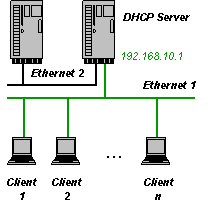
- Example 2: The server has 2 or more NICs and manages clients on one of the subnets
[General]
SUBNETMASK=255.255.255.0
ROUTER_1=192.168.10.1
DNS_1=192.168.10.1
[Settings]
IPBIND_1=192.168.10.1
IPPOOL_1=192.168.10.2-49
This manages the IP addresses 192.168.10.2 until 192.168.10.49. The DHCP Server binds only to one NIC with the IP address 192.168.10.1. The other NIC (Ethernet 2) is not touched by the DHCP Server. This is very useful if Ethernet 2 is your company LAN and you don’t want to interfere with it.
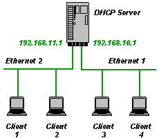
- Example 3: The server has 2 or more NICs and manages clients on two subnets
[General]
SUBNETMASK=255.255.255.0
ROUTER_1=192.168.10.1
DNS_1=192.168.10.1
[Settings]
AssociateBindsToPools=1
IPBIND_1=192.168.10.1
IPBIND_2=192.168.11.1
IPPOOL_1=192.168.10.2-49
IPPOOL_2=192.168.11.2-49
This manages the IP addresses 192.168.10.2 until 192.168.10.49 for Ethernet 1 and 192.168.11.2 until 192.168.11.49 for Ethernet 2. Please note the line AssociateBindsToPools=1. This option associates the IP Pools with the corresponding IP Binds. Without that option the DHCP Server would view all IPPOOL_x as one big IP pool independent of the subnet.
The different INI file sections
The INI file consists of sections for configuration purposes: [Settings], [DNS-Settings], [Servers] and database purposes: [General], [General_x], and [client section name].
The examples above contained the [Settings] section and the [General] section. The [Settings] section holds all the configuration data for the DHCP server itself. Most importantly the IP pools that the DHCP Server is supposed to manage. The idea behind the database sections is very simple. The DHCP Server tries first to obtain the requested information from the client section then form the [General_x] section and then from the [General] section. The client sections are created as clients connect. For example:
[00-E0-00-1C-AB-67]
IPADDR=192.168.10.11
AutoConfig=12/29/2007 18:37:26
LeaseEnd=1198953446
This section is added automatically by the DHCP Server when a client with the MAC address 00-E0-00-1C-AB-67 requests an IP address. Here, the IP address 192.168.10.11 has been assigned and the IP address will expire at a certain time which is stored as number of seconds since midnight (00:00:00), January 1, 1970. If the client section does not include all requested information, then the DHCP Server checks the [General_x] section and the [General] section.
The complete set of data that the DHCP Server transmits to the client is composed of the entries in the client section [00-E0-00-1C-AB-67], the [General_x] and the [General] section.
Please note that with V1.7 it is possible to use the client-identifier (option 61) instead of the mac address to specify client sections. See also the UseClientID setting defined in the INI file reference. In case of client-id based specifications, all the [00-E0-00-1C-AB-67] sections will actually be defined based on the client supplied option 61. This can be a name (ascii string) or a mac address.
The [General_x] sections are optional but needed to define NIC specific information. Where x is the same number as in IPBIND_x. It is possible to define NIC specific [General_x] sections, in case that the subnets have different subnet masks or different lease times. The following example is an extension of example 3 and defines a lease time of 1 hour for clients connected to Ethernet 1 and a lease time of 1 day for clients connected to Ethernet 2.
[General]
SUBNETMASK=255.255.255.0
ROUTER_1=192.168.10.1
DNS_1=192.168.10.1
[General_1]
LEASETIME=3600  ; default lease time of 1 hour
[General_2]
LEASETIME=86400  ; default lease time of 1 day
[Settings]
AssociateBindsToPools=1
IPBIND_1=192.168.10.1
IPBIND_2=192.168.11.1
IPPOOL_1=192.168.10.2-49
IPPOOL_2=192.168.11.2-49
Lease times are important when a client requests an IP address and all addresses in the IP pool are already assigned to other clients. In that case the client whose lease time has expired least recently is deleted from the INI file and the available IP address is used for the request. The lease time is calculated as the minimum of what the client requests and the LEASETIME configured in the INI file. Clients will request an extension of the lease in time before the lease expires. If the LEASETIME is set to only a few seconds then the network will be constantly full of traffic with lease extension requests.
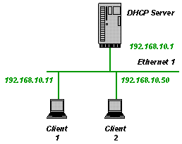
It is also possible to add client sections to the INI file manually. The following client section assigns the client with the MAC address 00-E0-00-1C-AB-68 the IP address 192.168.10.50.
[00-E0-00-1C-AB-68]
IPADDR=192.168.10.50
This is a static assignment and is not changed or deleted by the DHCP Server. It is important to not specify the AutoConfig=xxxxx entry in the client section, otherwise the DHCP Server would consider this as an automatically created client section. The INI file may contain static entries only. This can be a useful way of limiting the clients on the network to only known and allowed computers. The IPPOOL_x should be removed from the INI file in case of fully static assignments. Here is an example for fully static configurations:
- Example 4: Static configuration on one subnet
The INI file looks like this:
[General]
SUBNETMASK=255.255.255.0
LEASETIME=32000000 ; approx. 1 year
ROUTER_1=192.168.10.1
DNS_1=192.168.10.1
[Settings]
IPBIND_1=192.168.10.1
IgnoreUnknownClients=1
[00-E0-00-1C-AB-68] ; Client 2
IPADDR=192.168.10.50
[00-E0-00-1C-AB-67] ; Client 1
IPADDR=192.168.10.11
Please note the line IgnoreUnknownClients=1. This option prevents the DHCP Server from sending answers to clients that are not configured in the INI file.
DNS Server configuration
The [DNS-Settings] section consists of the settings for the integrated DNS server. This is a new feature of V1.8 and lets the DHCP Server on the same data (ini file) also handle DNS requests. This is done based on the IPADDR and Hostname entries of the configured clients. The supported DNS requests are A (IP->hostname) and PTR (hostname -> IP). If a client section in the ini file does not include the Hostname entry, then this client is not visible to the DNS Server (it has no name !). Example for a DNS configuration:
[DNS-Settings]
EnableDNS=1 ; if not set or set to 0, then DNS is not enabled
FORWARD=192.168.2.1 ; if set, then all requests that can not be fulfilled are forwarded to this address
DEFAULTIPADDR=192.168.10.1 ; if set, then all requests from not configured clients get this IP Address as an answer

[General]
DOMAINNAME=mydomain.local

...
Please note the DOMAINNAME in the example above. This really has to be stored in the [General] section (not [General_x]) and specifies the domain name suffix for the DNS requests. If a client is configured with hostname=linux_box_1, then linux_box_1 and linux_box_1.mydomain.local are both valid names for the client machine. EnableDNS is self explanatory, I guess.
The FORWARD setting defines one external DNS server that gets all the requests that the integrated DNS server can not answer. This feature is fairly rudimentary and works only with UDP.
The DEFAULTIPADDR setting is a very simple but effective security feature. If DEFAULTIPADDR is not set then the DNS server serves everybody as expected with resovled names. If it is set, then requesters with an unknown IP address get always the default ip address as an answer to all name resolution requests. The intention of this feature is to forward all unknown clients to a predefined default address (e.g. a web server with registration facility).
TFTP Server configuration
The [TFTP-SETTINGS] section consists of the settings for the integrated TFTP Server. This is a new feature of V1.9 and lets the DHCP server act as a tftp server. This is useful in network boot scenarios in combination with the BOOTP protocol. Please see the following ini file snippet as an example for a tftp configuration.
[TFTP-Settings]
EnableTFTP=1 ; if not set or set to 0, then TFTP is not enabled
PortRange=AUTO ; the ports used for TFTP are automatically chosen
WritePermission=0 ; if not set or set to 0, then write operations are denied
Root="c:\tftproot\" ; the server side pathname to the files served through the tftp protocol

...
No further configuration is required in the ini file. Please make sure that port 69 (tftp protocol port) is available through the firewalls.
HTTP Server configuration
The [HTTP-SETTINGS] section consists of the settings for the integrated HTTP Server. This is a new feature of V2.0 and lets the DHCP server act as a Web server. The main purpose of the Web server is to support life diagnostic information shown in a Web browser, but it can be used as a regular Web server as well (does not support CGI). Please see the following ini file snippet as an example for a http configuration.
[Settings]
PORT_80=50556 ; overrides the default port 80 to prevent collisions with other web servers

[HTTP-Settings]
EnableHTTP=1 ; if not set or set to 0, then HTTP is not enabled
Root="c:\httproot\" ; the server side pathname to the files served through the http protocol
Logfile="c:\dhcprv\httplog.txt" ; the http server logs all web access in this file

[content-type] ; mapping of filename extensions to content-types
.htm=text/html
.html=text/html
.css=text/css
.xsl=text/xsl
.jpg=image/jpeg
.png=image/png
.gif=image/gif
.ico=image/x-icon
.xml=application/xml
.txt=text/plain
The http server will serve all files (including sub directories) in c:\httproot. In addition to this two special “files” are supported and can be reached from the web browser: dhcpstatus.xml and dhcptrace.txt. These files do not exist in the http root folder but its content is generated on the fly by the DHCP Server. Please note that dhcpstatus.xml makes use of xsl translations to transform xml to html. The file dhcpstyle.xsl is part of the zip file and needs to be stored in the http root folder.
The DHCP status web page can be accessed through the following URL: http://127.0.0.1:50556/.
Since V2.9 the [HTTP-SETTINGS-ALIAS] section can be used to define aliases for URLs. This allows to redirect URLs to certain web pages. For example, if you want all requests to the /icons directory be replied with the favicon.ico then you may do the following:
[HTTP-SETTINGS-ALIAS]
/icons/*=favicon.ico
*=index.html
DOS-like wildcards are recognized and the aliases are handled from top to bottom. Meaning, in the example above, index.html file is replied if nothing else fits. Existing files always have highest priority, of course.
Support of multiple scopes and relay agent
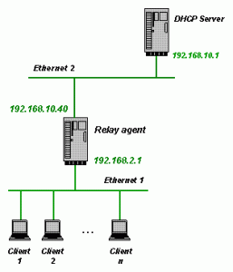
The relay agent support was added in V2.0. This includes the actual relay agent and the support of multiple scopes on the DHCP server side. A relay agent is needed if the clients to be served with IP addresses are in a different subnet than the DHCP server. This is almost always the case when a central DHCP Server is responsible for many different subnets. Instead of having as many DHCP servers as there are subnets, a relay agent per subset is used. To setup the dhcpsrv.exe to act as a relay agent requires the following INI file:
[Settings]
IPBIND_0=192.168.2.1 ; local IP address on client subnet
IPRELAY_0=192.168.10.1 ; IP address of central DHCP server
IPBIND_1=192.168.10.40 ; local IP address on server subnet
IPRELAY_1=192.168.10.1 ; IP address of central DHCP server
AssociateBindsToPools=1
All DHCP requests coming in from the client subnet will be forwarded to the DHCP server 192.168.10.1 and back to the client in return. The DHCP server itself needs to be configured with the following INI file:
[Settings]
IPBIND_0=192.168.10.1
IPPOOL_0=192.168.10.40-59 ; IP pool for directly connected clients
IPBIND_1=192.168.10.1
IPPOOL_1=192.168.2.2-254 ; IP pool for clients behind relay agent
AssociateBindsToPools=1

[General_0]
SUBNETMASK=255.255.255.0 ; subnet mask for directly connected clients
[General_1]
SUBNETMASK=255.255.255.0 ; subnet mask for clients behind relay agent
The DHCP server automatically matches the scope according to the network id of the client subnet. A total of 10 scopes (IPPOOL_0 to IPPOOL_9) is supported. Please note that the local scope needs to be the first defined. Easiest is to always make the local scope IPPOOL_0.
In both cases, relay agent and dhcp server, the IPBIND_x always defines the local IP address of the network interface card for receiving request and sending responses. Local scopes have the same network ID as the IPBIND_x and define their respective pool in IPPOOL_x. If the scopes have different subnet masks, then use the [General_x] sections for that.
The relay agent function is realized in conformance to RFC5107: DHCP server identifier override, RFC3046: DHCP Relay Agent Information Option, RFC3527: Link selection sub-option for the Relay Agent.
Multiple Server configurations
The [Servers] section is a new functionality in V1.8 and allows to virtualize the DHCP Server. It was already a suggested procedure to run the DHCP Server executable multiple times with seperate ini files, if more than one subnet with multiple IPPOOLs each need to be supported. This was not very user friendly and didn’t work for service installations. With the [Servers] settings this is now an integrated functionality. Here is an example on how the dhcpsrv.ini file looks like in this case:
[Settings]
InstallAsService=2 ; run as application
ShowBalloonMessages=1
NotifyTimeout=10000 ; delay after network changes detected in milliseconds

[Servers]
SERVER_1=dhcp1.ini
SERVER_2=dhcp2.ini
Two “virtual” DHCP Server instances are created with their own ini-file. All the sections and configurations can be specified in the dhcp1.ini or dhcp2.ini as usual. The settings and databases are kept seperately and behave as if two instances of the dhcpsr.exe would have been started with a dedicated ini file for each of them. The only [Settings] that are not “virtualized” are the ones shown in the example above: InstallAsService, ShowBalloonMessages and NotifyTimeout. They can not be “virtualized”, because they really define the behavior of the executable process (e.g. installation or icon in the tray). The same applies for the integrated http server: it is a process wide function and needs to be configured in the main INI file and not in the virtualized instances.
Please be aware that all IP addresses specified in the examples above need to be adopted to your particular network setup. See the complete INI file reference for all other configuration options.
Since V2.4.3, it is possible to define a display name per SERVER_x instance. This helps to get a better view of things in the integrated status web page. Here is an example on how to use it:
[Servers]
SERVER_1=dhcp1.ini
DISPLAYNAME_1="LAN Network"
SERVER_2=dhcp2.ini
DISPLAYNAME_2="Camera Network"
In all places where the status was shown for e.g. SERVER_1 now shows LAN Network instead.

